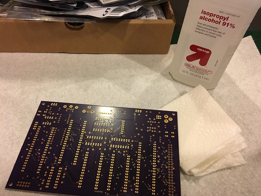
Following the manual, make sure you have all parts ready and organized. Next, clean the PCB with some alcohol and a paper towel.
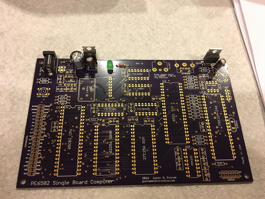
The first parts to be soldered into place comprise the power supply- an input jack to receive the power adapter, a diode, smoothing capacitors and voltage regulators that provide a stable 5 volts DC, and 3.3 volts DC, and a power LED (and associated resistor). These parts are installed first, so that you can test the power supply voltages after completing this step, without risking any other parts if there is any issue.
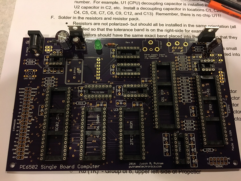
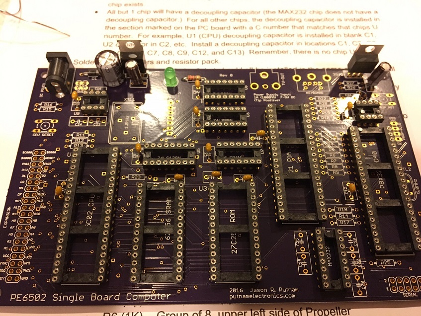
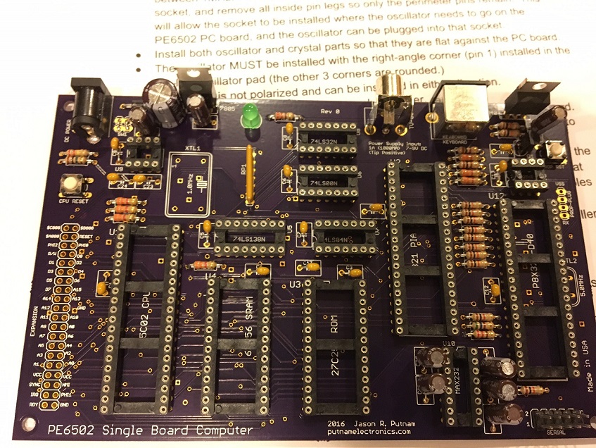
Next, install the chip sockets, paying attention to the pin-1 notch on the sockets; All vertical sockets have this notch on top, and all horizontal sockets have the notch to the left side.
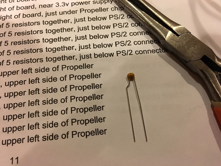
The decoupling capacitors, and one additional non-polarized capacitor are installed next. To do this neatly, all of these .1 uF capacitors have 1 leg bent so that the capacitor sort of resembles a capital letter "R". Then they are soldered into place, paying attention to mount the decoupling capacitors as close to the chip as practical.
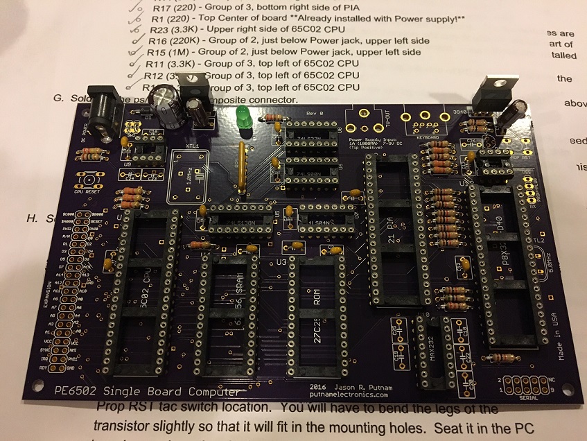
In the next step, the resistors are installed, and also a resistor pack is installed. This step is a bit of work, but when you're done, there is light at the end of the tunnel!
The PS/2 and the RCA video connector are soldered in next. As with the chip sockets before, and also with the expansion headers later, I use masking tape to hold the parts firmly/fully in place. Once they are soldered, the tape can be removed to reveal a perfectly installed part.
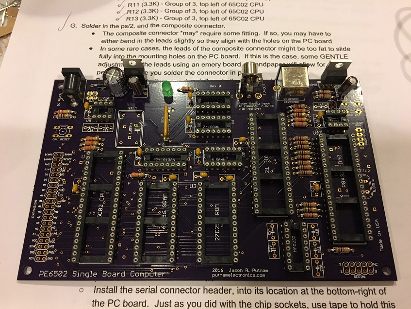
The serial interface is installed next. This involves installing the 10uF electrolytic capacitors (be mindful of the orientation guidance provided in the manual!), the serial header, a transistor, and one more .1 uF capacitor.
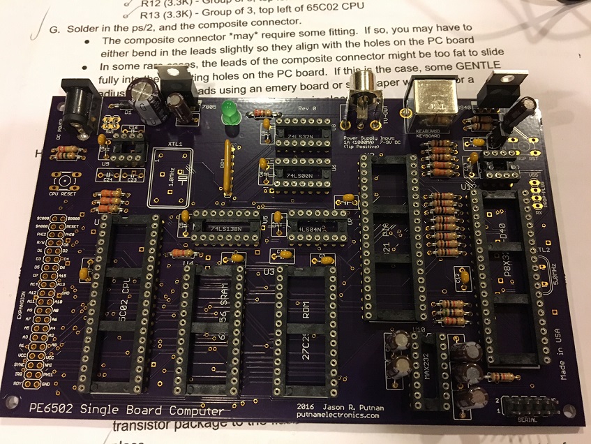
The reset tac switches, and three capacitors which are part of the timer reset circuit are installed now. There are two tac switch buttons; The one on the left (near the reset 555 timer) is for the CPU. The one on the right resets the propeller chip, which is an amazing 8-core microcontroller in its own right- on the PE6502 it handles all display output and keyboard input duties.
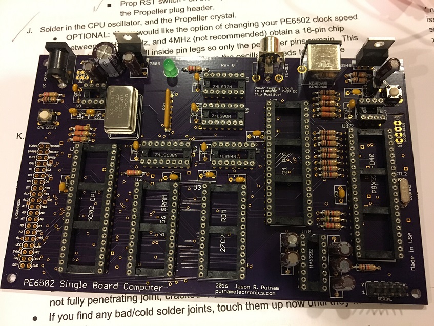
The crystals are installed next. You have an option here: the main CPU oscillator can be either installed directly into the circuit board, or, with the included special oscillator socket (it's the size of a 16-pin DIP socket, but only has pins at each corner) you can solder in the socket, and then plug the oscillator of your choice into the socket. Obviously, 1MHz is guaranteed to work- and I've personally tested up to 4 MHz without any issues noticed (your mileage may vary!) The 1 MHz oscillator is included. Also, the 5 MHz crystal is installed for the propeller chip.
Almost done now! Just one more step involving solder: Install the expansion header, and the propeller plug.
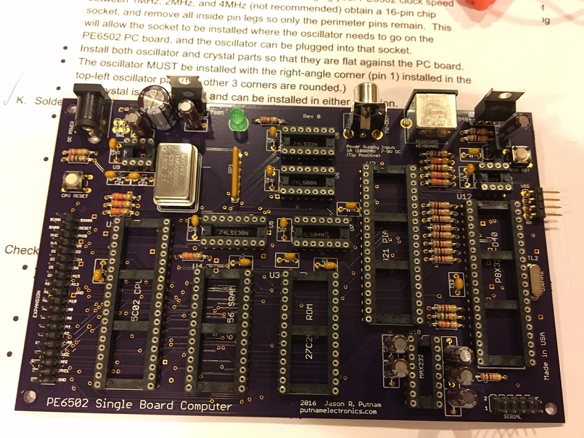
Ok. Now, all that is left are 3 easy steps:
1) Carefully inspect the solder side of the PE6502 computer, to ensure no solder bridges are present, and that all joints are properly soldered/all parts are installed.
2) Thoroughly clean the solder side of the PE6502 with rubbing alcohol and q-tips/paper towels, or maybe even rubbing alcohol with an old toothbrush and then dry with paper towels to remove all rosin splatters from the board.
3) Carefully install the chips (you may have to bend the legs carefully to ensure they all align with the sockets- and slowly push the chips into their sockets so they seat without bending any pins!) Also note: your kit will most likely come with a 65C21 PIA instead of the 6821 PIA. Both work equally well.
The 27C256 PROM will have been programmed for you in advance. The Propeller EEPROM will also be programmed in advance. Both the serial interface or using a propeller plug (not included) with the propeller header can flash an update into the propeller.
Congratulations! You're ready to use your new computer!